

Dock Ice Protection Systems
Is your dock a fragile target for shifting ice, or is it a resilient island in a frozen sea? Nature doesn't care how much you spent on your dock. Unless you build a resilient buffer zone, the ice will eventually win. Protecting waterfront infrastructure requires a shift from passive hope to active mechanical intervention. This guide examines the technical parameters of dock ice protection, focusing on the physics of water density and the mechanical systems designed to mitigate structural failure.
Dock Ice Protection Systems
Dock ice protection systems are engineered mechanical or pneumatic installations designed to prevent ice-related damage to permanent waterfront structures. These systems operate by disrupting the natural freezing process of surface water, typically in freshwater lakes or saltwater marinas. The primary objective is to maintain a BUFFERED ZONE—a controlled perimeter of open or agitated water—that prevents the surrounding ice sheet from making direct, static contact with pilings, frames, or flotation units.
In real-world applications, these systems are used where removing the dock for winter is cost-prohibitive or physically impossible. Fixed piers, crib docks, and large-scale marina slips are the most common candidates. Without these systems, structures are subjected to ICE PRESSURE, a relentless force generated by the thermal expansion of the ice sheet and vertical shifts in water levels. These systems serve as a mechanical barrier, ensuring that the dock remains decoupled from the ice sheet's movement.
How It Works: The Physics of Thermal Stratification
The efficacy of any ice protection system relies on the unique physical properties of water. Unlike most liquids, water reaches its maximum density at approximately 39.2°F (4°C). In a typical winter lake environment, "reverse stratification" occurs: the coldest, least dense water (32°F) sits at the surface, while the "warmest" and densest water (39.2°F) settles at the bottom.
Ice protection systems utilize one of two primary mechanical methods to leverage this thermal layering:
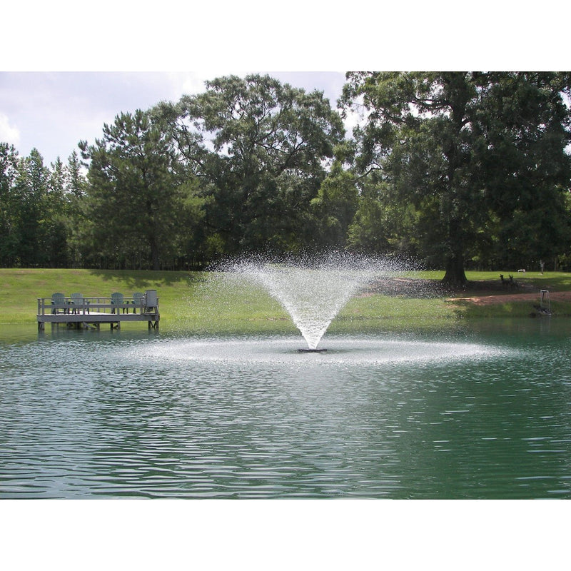
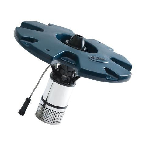
* Mechanical Agitation (Circulators): These units use a submersible motor and a high-pitched propeller to draw the 39.2°F water from the depths and thrust it toward the surface. The high-velocity stream of warmer water prevents ice crystals from bonding and provides enough thermal energy to melt existing surface ice.
* Pneumatic Aeration (Bubblers): An onshore compressor pumps air through weighted, perforated tubing (diffuser lines) placed on the lake bed. As the air bubbles rise, they create a "curtain" of moving water. This vertical lift pulls the warmer bottom water upward in a controlled, linear pattern, creating a precise BUFFERED ZONE around the dock's perimeter.
Both systems aim to neutralize the mechanical loads imposed by the ice. By maintaining a liquid state at the interface of the dock and the water, the structure is protected from "ice jacking"—where ice grips a piling and pulls it upward as water levels rise—and horizontal "shoving" caused by the expansion of the wider ice sheet.
Benefits of Active Ice Mitigation
The primary advantage of installing a dedicated protection system is the preservation of structural integrity against extreme mechanical stress. ICE PRESSURE is not merely a static load; it is a dynamic force that can reach several hundred pounds per square inch (psi) during rapid temperature drops.
Key measurable benefits include:
* Reduction of Vertical Displacement: By preventing ice from "locking" onto pilings, the risk of "jacking"—the gradual extraction of piles from the lakebed—is eliminated.
* Mitigation of Horizontal Shear: An open water buffer allows the surrounding ice sheet to expand and contract without transferring those lateral forces to the dock frame.
* Extended Infrastructure Lifespan: Reducing the annual cycle of stress and repair significantly lowers the total cost of ownership for waterfront property.
* Safety of Moored Vessels: For boat owners who keep vessels in the water, these systems prevent the crushing of hulls and the failure of through-hull fittings due to freeze-in.
Challenges and Common Mechanical Pitfalls
Designing an effective system is not as simple as submerging a motor. Several technical challenges can compromise efficiency or cause collateral damage.
Over-Clearing: A frequent mistake is creating a BUFFERED ZONE that is too large. While a massive area of open water looks impressive, it creates a "fetch"—a distance over which wind can move floating ice chunks. These chunks can then act as battering rams against the very structure the system is meant to protect.
Sediment Disturbance: In shallow water (less than 3 feet), powerful circulators can stir up lake-bottom sediment. This causes localized erosion around pilings, potentially undermining the dock’s foundation. It also releases trapped nutrients like phosphorus, which can lead to algae blooms in the spring.
Improper Mounting: Suspending units by ropes alone often leads to "recoil" or shifting, where the unit’s thrust pushes it out of the optimal position. Rigid dock mounts or weighted diffuser lines are necessary for maintaining a consistent protection zone.
Limitations and Environmental Constraints
Ice protection systems are not universal solutions and face realistic constraints.
Water Depth Requirements: Systems that rely on thermal stratification require a minimum depth (typically 3 to 4 feet) to access water at the 39.2°F threshold. In extremely shallow bays, there is no "warm" water to draw upon, and the system may only work through surface agitation, which is significantly less energy-efficient.
Electrical Reliability: These systems are entirely dependent on a stable power supply. A mid-winter power failure can allow the dock to freeze in within hours. Without a battery backup or a monitored alarm system, a temporary outage can result in catastrophic failure if the ice sheet subsequently shifts.
Regulatory Boundaries: Many jurisdictions require specific signage or lighting to warn snowmobilers and skaters of open water. Failure to comply with these local safety regulations can lead to legal liability and fines.
System Comparison: Circulators vs. Bubblers
Choosing between a propeller-driven circulator and an air-based bubbler depends on the dock configuration and environmental conditions.
| Factor | Propeller Circulator | Air Bubbler (Pneumatic) |
|---|---|---|
| Power Consumption | High (Amps: 5.0 - 10.0+) | Low to Moderate (Amps: 1.5 - 4.0) |
| Protection Pattern | Circular/Oval (Spot protection) | Linear (Perimeter protection) |
| Installation Depth | Needs 4ft+ for max efficiency | Effective in shallow and deep water |
| Noise Level | Low (Submerged) | Moderate (Onshore Compressor) |
| Maintenance | High (Seal checks/Zincs) | Low (Filter changes) |
Circulators are generally better for clearing large, localized areas like boat slips, whereas bubblers are superior for protecting long, thin dock perimeters.
Practical Tips for System Optimization
Maximizing efficiency requires precise calibration of hardware and timing.
* Integrate Thermostats and Timers: Running a system 24/7 is often unnecessary. A thermostat set to activate at 30°F, paired with a timer that runs the unit for 2–4 hour cycles, can reduce electricity costs by over 60% while maintaining an adequate BUFFERED ZONE.
* Optimize Unit Angle: For circulators, angling the unit upward at a 30-to-45-degree angle provides the best balance of thermal lift and surface agitation. Avoid pointing units directly at the shoreline to prevent erosion.
* Periodic Anode Inspection: In brackish or saltwater environments, sacrificial zinc anodes must be checked monthly. Corrosion on the motor housing can lead to seal failure and total motor burnout.
* Use Weighted Airline: For bubbler systems, ensure the diffuser tubing is "self-sinking." Standard tubing will float when filled with air, disrupting the curtain and leaving sections of the dock vulnerable.
Advanced Considerations: Mechanical Seals and Thrust Metrics
Professional installers focus on the "thrust-to-amp" ratio. A high-efficiency 1/2 HP motor that produces 30 lbs of thrust is often more effective than a poorly designed 1 HP motor that produces 35 lbs of thrust at double the power cost.
Mechanical Seal Integrity: Most high-end circulators use carbon-ceramic mechanical seals. These are engineered for long-term submersion but are vulnerable to "fishing line wrap." Inspecting the propeller shaft for debris before the first freeze is a critical preventive measure.
Fluid Dynamics of the Bubble Curtain: The size of the bubbles in a pneumatic system dictates the efficiency of the "water lift." Fine-pore diffusers produce smaller bubbles with a higher surface-area-to-volume ratio, which moves more water per CFM (cubic feet per minute) of air than coarse-bubble systems. This optimization is vital for deep-water marinas where the air must travel 15+ feet to reach the surface.
Scenario: Protecting a 40-Foot L-Shaped Dock
Consider a standard 40-foot L-shaped fixed dock in a northern lake with an average depth of 6 feet.
1. Hardware Selection: A 1/2 HP circulator is placed at the outer corner of the "L."
2. Positioning: The unit is mounted 4 feet deep, angled 45 degrees toward the "crook" of the L.
3. The Result: The circular thrust pattern covers the high-stress corner where ICE PRESSURE typically converges.
4. Secondary Protection: If the long 40-foot approach is also vulnerable to jacking, a bubbler line is run along the pilings to provide a linear BUFFERED ZONE that the circulator cannot reach.
This hybrid approach ensures that no single point of failure leaves the structure exposed to the ice sheet.
Final Thoughts
Efficient ice protection is a matter of mechanical precision rather than raw power. Understanding the interaction between thermal stratification and structural loads allows for the creation of a BUFFERED ZONE that effectively isolates a dock from the destructive force of ICE PRESSURE.
Implementing these systems requires a balanced approach to hardware selection, placement, and automated control. By focusing on the data—amps, thrust, and depth—waterfront owners can move from reactive repairs to proactive preservation.
Experimentation with timing and angles during the first few weeks of freezing will reveal the unique "flow signature" of your shoreline. Applying these technical principles ensures that when the spring thaw arrives, your dock remains exactly where you left it.